 Co., Ltd.")

NEWS CENTER
Filter insertion loss characteristics, network impedance determination
Release time: 2020-04-28
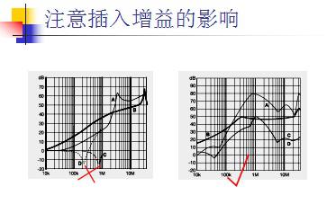
From the above figure, we can see that the differential mode insertion loss of the filter has a great relationship with the network impedance to which the filter is connected. 99% of filter manufacturers only provide curves A and B, but not C and D. The selection of the filter by the manufacturer's curves A and B alone does not guarantee that the test will pass.
When the network impedance connected to the input and output of the filter is very different, the insertion loss characteristics of the filter will be severely reduced, and sometimes even the insertion gain phenomenon occurs. Electronic engineers need to pay attention to this feature. Because at this time, the filter will amplify the disturbance of certain frequencies.
The insertion loss characteristics of the two filters shown in the figure above, the corresponding filter on the right is much better than the corresponding filter on the left. This is because the filter insertion gain on the right is not only small, but also occurs at lower frequencies. Since the lowest frequency of the conducted emission test for commercial equipment is 150kHz, the insertion gain below 100kHz will not cause the test to fail.
Of course, for the electromagnetic compatibility CE102 test, since the lower frequency limit is 10kHz, even the right insertion loss characteristic may not meet the requirements. In particular, when the frequency of the switching power supply is 40kHz, the conducted disturbance may be amplified by the filter.
keyword:
Taiwan Corporation
Address: No. 9, Gaocheng 9th Street, Bade City, Taoyuan County,
Tel: 03-369-4878
Shenzhen Business Office
Address: Room
, Building 637, 619 Bagua 1st Road, Futian District, Shenzhen Tel: +8613713787430
Shanghai Business Office
Address: Room
, 1004, Lane 20, 111, Zhentai Road, Baoshan District, Shanghai Tel: +8613917764177

WeChat Public Number
Mobile website
Learn more about Hongqing Electronics business consulting information
Tel: +86769-86636536
Fax: +86769-86636536
Copyright©2023. All Rights Reserved. Hongqing Electronics (Dongguan) Co., Ltd.
Copyright©2023. All Rights Reserved.
Hongqing Electronics (Dongguan) Co., Ltd.